Jonathan Rodgers
Additive Manufacturing & Design Engineer

CAD, Automation, and Production Workflow Engineering

Feel free to download my resume and portfolio and feed them to an AI assistant for a summary of work

Selected engineering work / November 2026

Problems worth understanding.
Solutions worth testing.

I'm Jonathan Rodgers. My work combines additive manufacturing, mechanical design and process improvement. These projects document the problem, what I contributed, how the approach was evaluated and what the evidence actually supports.

Memphis, TennesseeManufacturing / R&D / Product developmentjonathanrdgrs@gmail.com
7Selected engineering studies
3Professional environments and independent work
2026Portfolio updated

Explore the work

Open a project for the full methods and limitations.

Selected case studies

Observed results are distinguished from estimates and ongoing research.

01

HP powder management

uLab Systems / Production material-flow redesign

Completed builds were being held in occupied build units because powder recovery and unpacking could deadlock when assigned recycled-material barrels were bypassed.

32 to 14 build units required on the production floor; 18 freed for repair or swap use. No further reported deadlocks through October 2026.
Read the full engineering case study

Problem

Processing stations had assigned recycled-powder barrels, but operators sometimes bypassed them when replenishing station tanks. Recycled-powder barrels filled while powder was pulled from the auto-unpacker instead. Recovery and unpacking could then stall, leaving completed builds queued and build units occupied. Operators sometimes discarded recoverable powder to make room.

Approach

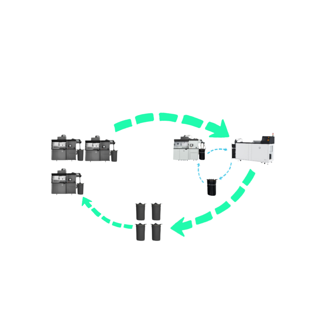
A four-barrel circulation and rotation method gave recovered powder a defined route and made the intended sequence easier to follow. The procedure addressed recycled-powder flow and replenishment across stations.

My contribution

I identified the material-flow bottleneck, co-developed the routing method with another engineer, tested the process and wrote the SOP. Maintenance and production personnel implemented the operating steps; I checked adoption and compliance.

Outcome and limits

The workflow was trialed in early 2026 and documented in April. As of October 2026 no further powder-management deadlocks had been reported. Avoided powder waste was not formally quantified.

Material circulation concept illustrating the recycled-powder routing method.
02

Dental CAD automation

Cagenix / Full-arch restoration design

Routine zirconia restoration design required repeated scan alignment, coping geometry, cutbacks and cleanup across Geomagic Wrap and Siemens NX.

About 30 minutes to 5 minutes of hands-on work per routine case in timed tests, approximately an 83% reduction.
Read the full engineering case study

Problem

Manual operations were difficult to train and scale, particularly where advanced CAD knowledge and application switching were required.

Approach

Automated repeatable geometry operations: coping-height determination from mesh intersections, cutback preparation using macros, and zirconia or PMMA workflow selection while keeping unusual cases under experienced review.

My contribution

I devised and coded the Python coping-height method using a geometric probe to locate suitable extrusion height, recorded the original cutback macro, adapted selection and offset for PMMA, and helped test integration. A collaborator built additional automation and SQL-driven workflow selection. I primarily tested, rather than developed, the separate scan-alignment automation.

Outcome and limits

Five production-oriented cases with different implant positions and geometries were tested, with downstream ceramist feedback. The process remained in production at my departure in January 2025. This was not a clinical outcome study.

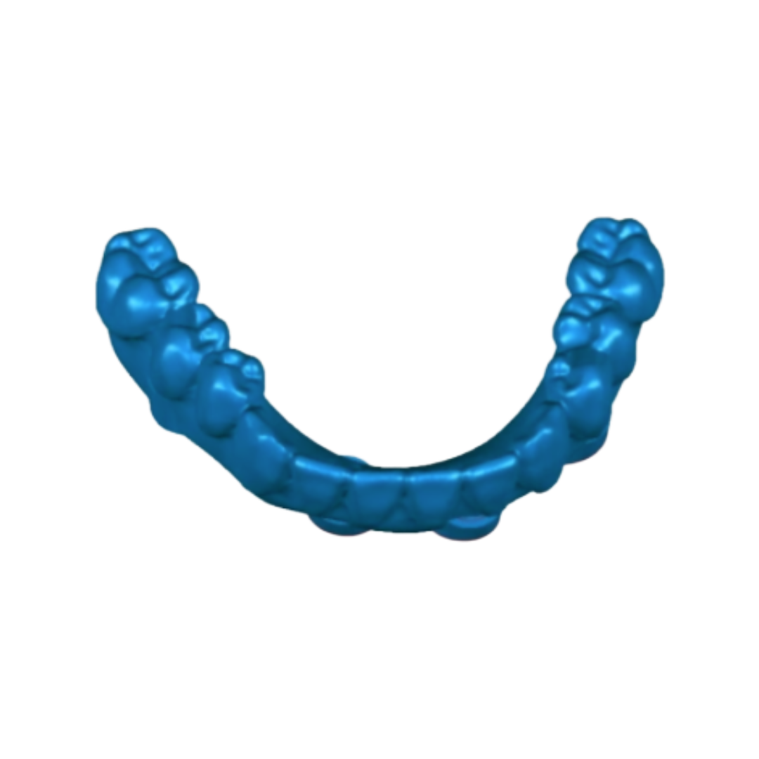
Illustrative dental restoration CAD geometry, not a screenshot of the automation running.
03

Distal flare and dimensional distortion

Cagenix comparative study / Follow-on independent research

An exploratory comparison of dental aesthetic-guide geometry printed with Stratasys J5 PolyJet, Formlabs Fuse 1 SLS and Formlabs Form 3B SLA showed region-dependent dimensional deviations. Posterior flare appeared in all three specimens.

Exploratory SLA bracing trial: approximately 50% less distal flare after crossbar removal than the unbraced model. Predictive compensation remains unvalidated.
Read the full engineering case study

Observation and measurement

The original evaluation used visual inspection, Imetric4D Li2 scans and Geomagic Wrap comparisons against the nominal CAD model. Distinct spatial deviations were observed for each material and process. The investigation was exploratory and did not include documented independent replication or measurement-uncertainty estimates.

Experimental intervention

I modified the SLA arch to include an integral crossbar connecting both distal ends. While attached, the crossbar restrained the arch during post-curing and eliminated the observed flare. Once removed, a subsequent scan showed approximately 50% less distal flare than the unbraced case. This comparison alone does not identify the cause of deformation.

Working hypothesis

Unequal effective strain between inner and outer regions of a curved thin-walled part may contribute to bending and distal displacement. The outer curved surface has more area than the inner surface, but area difference has not been shown to drive the observed deformation. Cure or thermal history, material behavior, orientation and constraints remain competing explanations.

Current research direction

I am developing simplified U-shaped and other non-dental curved specimens, with controlled wall thickness and repeatable scan positioning, to compare as-printed and post-processed deviations across polymer AM technologies. Fixture and specimen preparation are ongoing; this is not a completed validation.

Intended engineering outcome

The objective is to investigate whether a repeatable process- and geometry-dependent effective shrinkage or distortion coefficient can be estimated, and whether that model could inform deliberate CAD pre-distortion to counter expected distal flare. No transferable coefficient or validated compensation algorithm has been established.

Research questionCan distortion be characterized, then compensated for in the source geometry?Curved non-dental test specimens / repeatable 3D metrology / process-specific response
04

HP fusing-lamp reliability

uLab Systems / 11-printer HP Multi Jet Fusion fleet

Premature lamp replacements interrupted production. Powder intrusion raised concerns about cooling-air pathways and service life across a fleet with four lamps per machine.

Average recorded lamp life: approximately 365 to 390 hours in early 2025 versus approximately 670 hours in early 2026; observational comparison, not proof of causality.
Read the full engineering case study

Approach

Introduced inspection and cleaning expectations for the chamber supplying lamp cooling fans, reviewed lamp replacement histories and operating hours, and assessed preventive-replacement intervals against the observed service-life distribution.

My contribution

I investigated the powder-intrusion path, established monthly maintenance expectations, analyzed MaintainX records and proposed consideration of preventive lamp replacement around 800 to 1,000 operating hours. Technicians performed and recorded maintenance. I later flagged weakening compliance.

Outcome and limits

A May 2026 analysis showed the difference in recorded average service life. Utilization, maintenance compliance and preventive replacement may influence the comparison. The policy recommendation was a modeled risk-management decision. Dollar savings were excluded pending reconciliation of warranty claims, replacement classifications and utilization.

Reliability investigationInspect. Record. Compare. Standardize.MaintainX service history / maintenance compliance / preventive-replacement modeling
05

R1/D independent engineering study

Independent project / 1968-era single-seater / In development

An ongoing study of a purpose-designed vintage-era single-seater, using vehicle-level packaging, suspension design, structural calculations and iterative CAD to understand interconnected engineering decisions.

Integrated CAD assembly and structural iterations completed. A 6 kN vertical upright FEA case and aerodynamic simulation informed revisions; physical validation remains ahead.
Read the full engineering case study

Purpose

The project began as an investigation into why automotive uprights are designed differently. A 1968-era single-seater became a way to study vehicle architecture, technical terminology and unfamiliar disciplines through design.

Approach

I use research and technical documentation, seek input from relevant specialists and examine CAD geometry with calculations and simulations. Engineering decisions are revisited when a constraint or result warrants it.

Engineering decisions

Front upright FEA showed stress concentration at a lower control-arm pickup. Two redesigns led to a tab-and-slot feature intended to route bump loads into the upright body. At vehicle level, I changed from an all-aluminum monocoque concept to a dual-sponson layout with machined bulkheads after evaluating fabrication, cost and access. I examined the revised concept against a stiffness target using closed-section torsion calculations.

Current stage and limits

The project includes CAD assembly work, suspension geometry, calculations and structural iterations. Combined-load and durability studies remain open. October 2026 airflow simulation indicated positive lift, which informs further design work. Fabrication and testing are not yet complete.

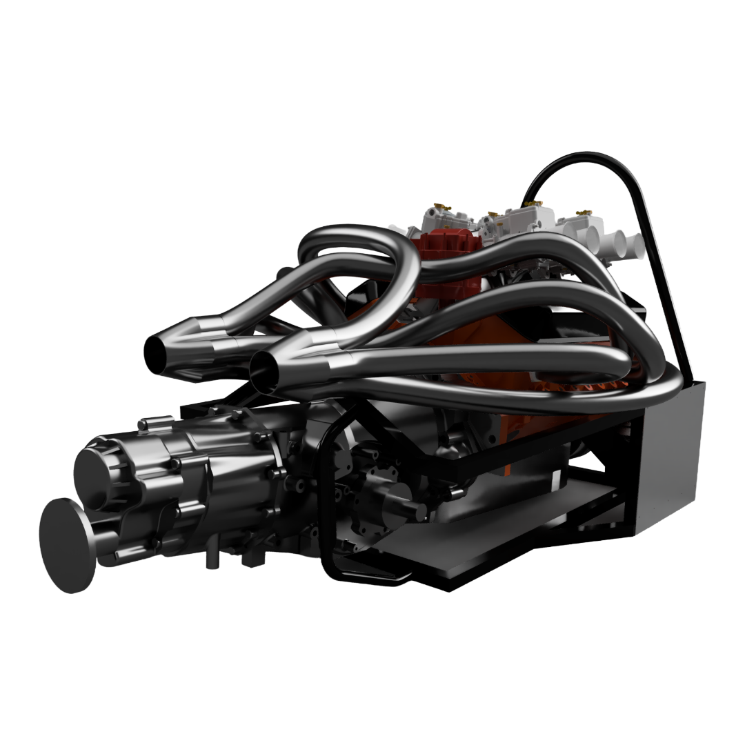
R1/D CAD assembly, a design study rather than a completed or tested vehicle.
Front upright pickup geometry.
Brake and hub packaging study.
06

Miata cupholder extender

MentaPrints / New product development and licensing

A removable cupholder riser was developed for a Miata owner who wanted better drink retention without permanent interior modifications or a visually intrusive accessory.

Licensed to Flyin’ Miata after direct-market validation; a manufacturing-transfer revision reduced material use by approximately 10%.
Read the full engineering case study
Problem

The part needed to raise the factory cupholder, retain drinks on demanding roads, avoid damage and match the existing interior design.

Solution

I developed a PETG extender with controlled interference, material compliance and locating tabs, plus an optional discreet zip-tie slot.

My contribution

I translated the request into requirements, iterated two prototypes and arranged testing in the customer vehicle. After over ten months of direct sales I forecast retail potential for Flyin’ Miata. Their test print informed another revision to fit their machine and material tolerances and increase the inner radius.

Outcome and limits

Testing on the Tail of the Dragon produced no reported spills. Direct sales informed an approximately $5,000 annual gross-retail-sales forecast for Flyin’ Miata, not actual royalty receipts. The company approved the revised design for production, with approximately 10% less material consumption.

Finished removable extender installed in a Miata interior.
07

Veloster badge redesign

MentaPrints / Design for manufacturing and process improvement

Custom printed automotive badges had inconsistent visible finishes and lengthy multicolor print cycles that made building inventory difficult.

Per-set printer time reduced from 240 to 90 minutes, a 62.5% decrease, plus approximately 2 minutes of bonding.
Read the full engineering case study
Problem

Occasional surface-quality complaints and four-hour printing time per two-badge set constrained the production process.

Solution

I separated the foreground and backing into independent components, printed display faces against the build plate, and introduced cyanoacrylate bonding.

My contribution

I designed the split-part architecture, adjusted print orientation and production setup, and introduced bonding. After a customer noticed backing flex without separation, I added a second rear adhesive application.

Outcome

Surface-finish complaints stopped following the redesign, and no further bonding complaints were reported after the corrective step. Reduced print time made holding finished inventory practical rather than relying only on print-on-demand.

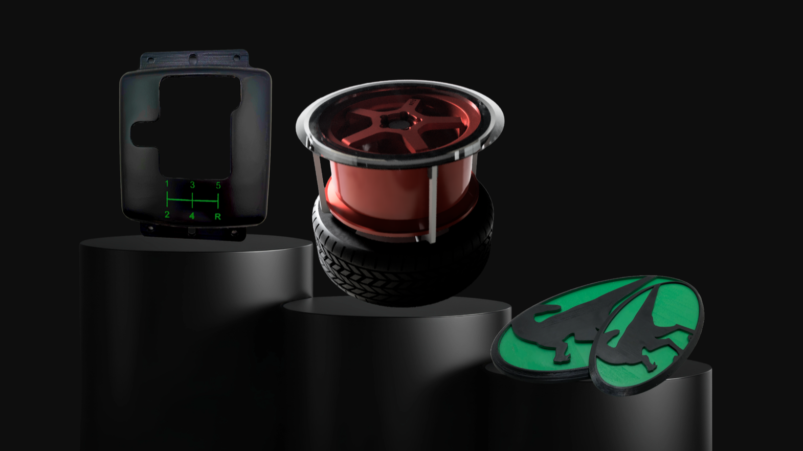
Exploded CAD view of a three-piece badge variant showing separate decorative and backing geometry.